1. Manual operation
a. Pull the clutch handle towards the handwheeluntil itis upright.
b. Ifthe handle is notupright, pull itagain andturn the handwheel slowly
c. Clockwise is the closed direction andcounterclockwise is the open direction.
d. Do not operate manually afterthe actuatoris energized, and the handle will be restored to its original position automatically bythe intemalclutch mechanism.
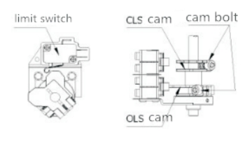
2. Limit switch setting
a. Pull the handle for manual operation and rotate the handwheel to make the actuatorrun to the original position.
b. Loosen the cam retaining boltwith a wrench, and rotate the cam to achieve the required adjus tment angle (according to actual requirements ofthe valve) andtighten the boltagain.
3. Torque switch
a. Torque switch has been set before delivery, the user does not need to setthe switch again.
Note: We cannot guarantee the performance ifthe switch is reset by the user.
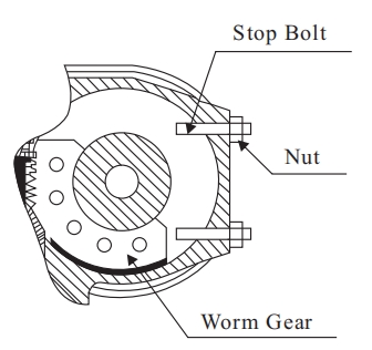
4. Setting ofstop bolt
a. When the errormore than 5°, need to readjust set retaining bolt.
b. When setting, remove the stop bolt by 2 turns and tighten the nut.
5. In dicator setting
a. Make the actuatorrun to the closed position androtate the actuator byhand.
b. Align the number ofthe lens in the direction.
c. Tighten the bolts (be carefulnot to touch the side ofthe indicator disc).
Note: factory set, usually does notneed to set again.
6. Attention for connection
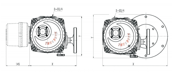
a. The cable interface is G3/4″ screw hole, sealed with plug before delivery.
b. If the user does not use either cable interface, please keep the plug as it is.
c. Please sealthe interface after wiring to prevent water inflow.
d. If the user use explosion-proof actuator, be sure to use same level connection components. Ifusers use ungualified components, we cannot guarantee the performance ofexplosion-proof actuator.
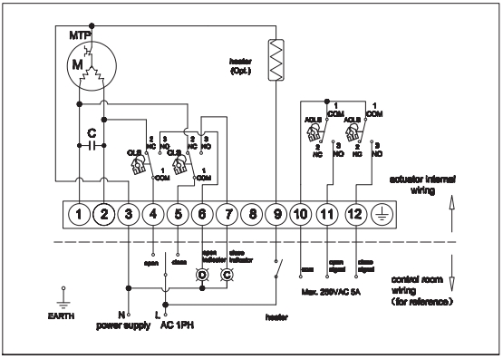
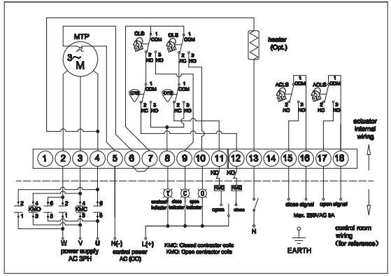
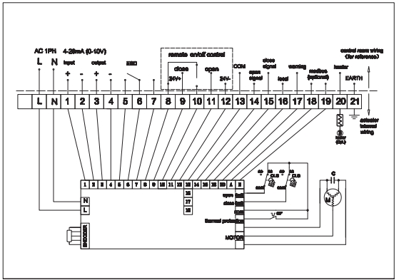
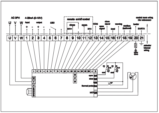
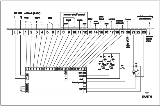
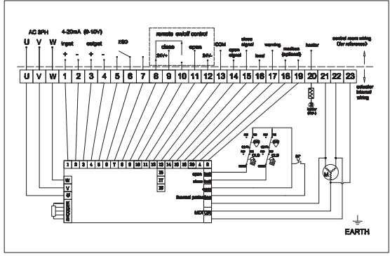
7. Electrical wiring
a. A wiring diagram (inside the electrical hatch cover) is attached to the actuator.
b. Wiring according to the wiring diagram provided, such as power supply, control power supply. internal wiring and grounding, etc. Ifnecessary, the external electrical source is from the dryer to keep the actuator dry.
d. Make sure the terminals are firmly connected.
e. Make sure that an external controller operates only one actuator.
Can not operate more than 2 sets actuators at one time).
f. Make sure the actuator is clean and free ofsundries after wiring.
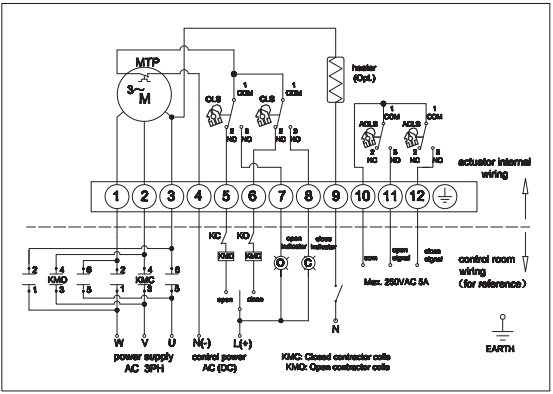
8. Check the rotation direction
a. For three-phase actuator, the rotation direction of the actuator should be checked before the electric operation (operator).
b. Ifthe direction ofoperation is incorrect, the limit switch will not work, resulting in plug damage or motor overheating.
c. Manually put the actuator in the position of 50% on (oroff), power the actuator, and confirm the direction ofrotation.
d. Ifthe signalis on, the actuator will rotate and run in the open direction, then the direction is correctBut ifyou go to the other way, you need to change the wiring and switch any 2 ofthe 3 power cords.
e. Check the rotation direction again and confirm it.
Trial operation
l. Make sure to check the rotation direction of the actuator before operation.
2. Check the function of limit switch and torque switch, direction of indicator and space heater.
3. Make sure the action of the handle is normal (clutch handle)
4. Check the indicator light on the control panel.
5. After the trial operation, please tighten the 4 bolts of the electrical hatch cover.
Maintenance
1. The actuator has been filled with the lubricants, it generally doesn’t need to add lubricants during norma.
2. It’s better to keep the power supply for the actuator and have a run test every week regularly.
3. For better the performance of the actuator, it is highly suggested to do the regular inspection and maintenanceonce year, together with checking the action status, surface corrosion, ect.